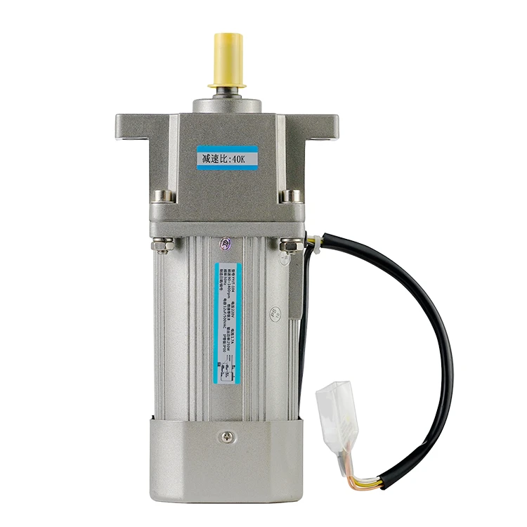
Measure the armature circuit resistance of a PMDC motor
2024-06-28 14:05:08
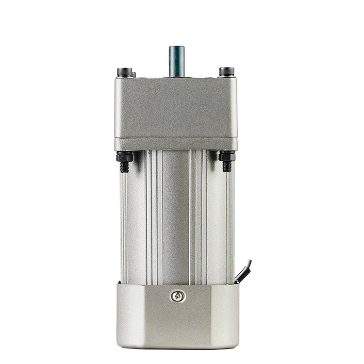
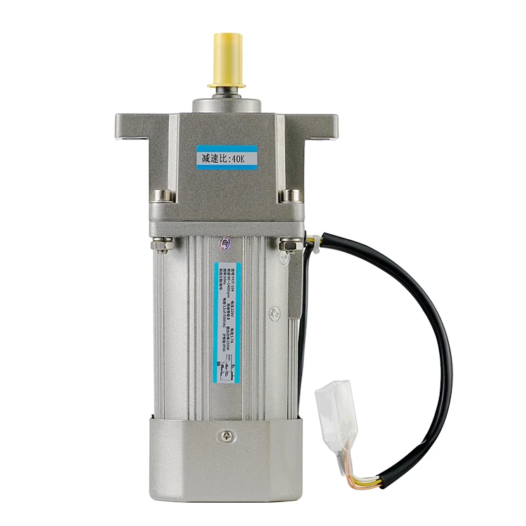
Measuring the winding resistance of a permanent magnet DC (PMDC) motor is a logical first step in troubleshooting when it stops working altogether or operates improperly. This makes it easier to identify if there is an open circuit or a short circuit between two windings in the same motor, between a winding and ground, or between turns of the same winding. When utilizing an ohmmeter on an AC motor or brushless DC motor, this procedure is simple; nevertheless, it becomes more difficult when dealing with a gearmotor or brush type (PM) DC motor.
Understanding Armature Circuit Resistance
Before delving into the measurement process, let's gain a deeper understanding of the armature circuit resistance in PMDC worm gear motors. Armature resistance plays a pivotal role in the performance of PMDC motors. The armature circuit consists of the armature winding, commutator, and brushes, it directly impacts the motor's speed, torque, and heat dissipation. The resistance in this circuit affects the current flow and voltage drop, influencing the motor's performance, efficiency, and temperature rise. A higher resistance typically leads to reduced current flow, diminished torque, and consequently, a lower motor speed. Conversely, very low resistance may indicate shorted windings, leading to overheating and potential motor failure. Measuring the armature circuit resistance allows us to assess the condition of the armature winding, detect any potential faults, and determine if the resistance is within the manufacturer's specifications.

Importance of Armature Circuit Resistance Measurement
- Identifying potential faults early: A significant increase in armature resistance may indicate issues like shorted turns, winding damage, or contamination, which can impede motor performance and reliability.
- Perform Troubleshooting: If a motor exhibits abnormal behavior or fails to function properly, measuring the armature circuit resistance can help identify potential issues and guide further troubleshooting steps.
- Assess Motor Performance: The armature circuit resistance directly affects the motor's electrical characteristics, including voltage drop, current flow, and power output. Accurate measurement ensures the motor is operating within its specified parameters.
Tools Required
- Digital Multimeter: A precision instrument capable of measuring resistance values accurately.
- Temperature Measuring Device: To note the armature’s temperature during measurement.
Measuring Armature Circuit Resistance
- Preparation: Ensure the motor is disconnected from its power source to prevent any electrical hazard. Record the ambient temperature and the armature’s temperature, as resistance varies with temperature.
- Access the Armature Circuit: This may involve partially disassembling the motor to access the terminals of the armature windings directly.
- Setting the Multimeter: Set the digital multimeter to the resistance measuring mode, often denoted by the omega (Ω) symbol. Choose a suitable resistance range if the multimeter isn't auto-ranging.
- Connect the Test Leads: Connect one test lead to the positive (red) terminal of the multimeter and the other test lead to the negative (black) terminal.
- Connect the Test Leads to the Motor: Connect one test lead to the positive brush or commutator segment and the other test lead to the negative brush or commutator segment. Ensure a secure connection is established.
- Take the Measurement: Read the resistance value displayed on the multimeter. This value represents the armature circuit resistance of the PMDC motor. Compare this value to the manufacturer's specifications to assess the motor's condition.
- Temperature Correction: If necessary, apply temperature correction to the measured resistance value, using the standard formula or values provided in the motor's documentation.
- Repeat the Measurement: For accurate results, it is advisable to take multiple measurements and calculate the average resistance value. This helps minimize any measurement errors or variations.
Troubleshooting and Interpretation
- Higher Than Expected Resistance: Indicates potential open circuits or damaged windings. Further investigation may be required to pinpoint the issue.
- Lower Than Expected Resistance: Could suggest shorted windings or other anomalies leading to low resistance paths within the armature.
Conclusion
Measuring the armature circuit resistance of a PMDC motor is a fundamental diagnostic tool that offers insights into the health and efficiency of the motor. The armature circuit resistance directly influences motor performance, efficiency, and reliability. Through careful and regular measurements, you can predict and prevent potential failures, ensuring the longevity and reliable operation of these vital components in countless applications.
See What Lunyee Can Do For You
Contact Us
- 8619149417743
- +86-0371-5562 0274
- [email protected]
- Zhengzhou, Henan Province, China
- Mon-Fri: 9:00 - 18:00
