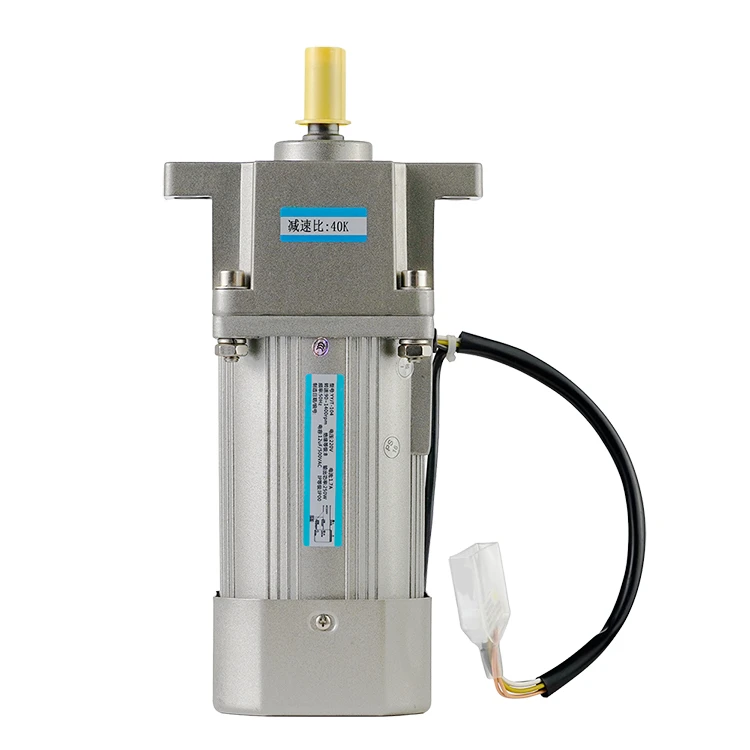
Stepper Motors and Their Selection Calculation Method
2023-12-27 09:29:20
A stepper motor is a type of motor that rotates the shaft through a stepping motion, i.e., moving in fixed angles. Its internal construction allows it to function without sensors, and by simply calculating the number of steps, you can determine the exact angular position of the shaft. This feature makes it suitable for various applications. Let's learn about stepper motors and their selection calculation method.
Working Principle of Stepper Motors
Like all motors, a stepper motor also consists of stationary parts (stator) and moving parts (rotor). The stator has toothed projections wound with coils, and the rotor is made of permanent magnets or variable reluctance iron cores. We will discuss different rotor structures in more detail later. The cross-sectional diagram of the motor shown below has a variable reluctance iron core rotor.
The basic working principle of a stepper motor is as follows: one or more stator phases are energized, the current through the coil produces a magnetic field, and the rotor aligns with this magnetic field; different phases are sequentially energized, causing the rotor to rotate a specific angle and finally reach the desired position. The figure below shows its working principle. First, coil A is energized and produces a magnetic field, causing the rotor to align with it; when coil B is energized, the rotor rotates clockwise 60° to align with the new magnetic field; when coil C is energized, the same situation occurs. The color of the small teeth on the stator in the figure below indicates the direction of the magnetic field produced by the stator coil.
Types and Construction of Stepper Motors
The performance of a stepper motor (regardless of its resolution/step angle, speed, or torque) is affected by the construction details. At the same time, these details may also affect the control method of the motor. In fact, not all stepper motors have the same internal structure (or construction) because the configuration of their rotor and stator is different.
Rotor
There are basically three types of rotors in a stepper motor:
- Permanent magnet rotor: The rotor is made of permanent magnets, which aligns with the magnetic field produced by the stator circuit. This type of rotor can ensure good torque and has braking torque. This means that the motor can resist (although not very strongly) changes in position, even if the coil is not energized. However, its disadvantage compared to other rotor types is that its speed and resolution are relatively low. The figure below shows the cross-sectional view of a permanent magnet stepper motor.
- Variable reluctance rotor: The rotor is made of iron cores, which have a special shape that can align with the magnetic field. This type of rotor is easier to achieve high speed and high resolution, but the torque it produces is generally low, and it has no braking torque.
- Hybrid rotor: This type of rotor has a special structure; it is a combination of permanent magnet and variable reluctance rotors. Its rotor has two axially magnetized magnetic hats, and there are alternating small teeth on the magnetic hats. This configuration enables the motor to have the advantages of both permanent magnet and variable reluctance rotors, especially high resolution, high speed, and large torque. Of course, higher performance requirements mean more complex structures and higher costs. When coil A is energized, the small tooth of rotor N magnet hat aligns with the S-magnetized stator tooth. At the same time, due to the structure of the rotor, rotor S magnet hat aligns with the N-magnetized stator tooth. Although the working principle of the stepper motor is the same, the actual motor structure is more complex, and the number of teeth is more than shown in the figure. A large number of teeth can make the motor obtain extremely small stepping angles, as small as 0.9°.
Stator
The stator is a part of the motor responsible for producing the magnetic field that aligns with the rotor. The main characteristics of the stator circuit are related to its phase number, pole pair number, and wiring configuration. The phase number is the number of independent coils, and the pole pair number indicates the number of main tooth pairs occupied by each phase. Two-phase stepper motors are most commonly used, while three-phase and five-phase motors are less commonly used.
Stepper Motor Control
From the previous text, we know that the motor coils need to be energized in a specific sequence to produce a magnetic field that aligns with the rotor. The devices that provide the necessary voltage to the coils to make the motor run normally include the following (starting from the device closest to the motor):
- Transistor Bridge: A device that physically controls the electrical connection of the motor coils. Transistors can be seen as electrically controlled switches. When they are closed, the coil is connected to the power source, and current flows through the coil. Each phase of the motor requires a transistor bridge.
- Pre-driver: A device that controls the activation of transistors. It is controlled by an MCU to provide the necessary voltage and current.
- MCU: A microcontroller unit that is usually programmed by the motor user to generate specific signals for the pre-driver to obtain the desired motor behavior.
The following diagram is a simple schematic of the stepper motor control scheme. The pre-driver and transistor bridge can be integrated into a single device, known as a driver.
Types of Stepper Motor Drivers
There are various types of stepper motor drivers available on the market, each with different features for specific applications. The most important feature is the input interface. The most common types of input interfaces include:
- Step/Direction (Step/Direction) – Sending a pulse to the Step pin causes the driver to change its output and move the motor one step. The direction of rotation is determined by the level on the Direction pin.
- Phase/Enable (Phase/Enable) – For each phase winding, Enable determines whether that phase is energized, and Phase determines the direction of current flow.
- PWM - Directly controls the gate signals of the upper and lower FETs.
Another important feature of stepper motor drivers is whether, in addition to controlling the voltage across the coils, they can control the current flowing through the coils:
A driver with voltage control can adjust the voltage across the coil, resulting in torque and step speed that only depend on the motor and load characteristics.
A current-controlled driver is more advanced because it can regulate the current flowing through the source coil, better controlling the generated torque, and thus better controlling the dynamics of the entire system.
Stepper Motor Drive Technology
Stepper motors mainly have four different drive technologies:
- Waveform Mode: Only one phase is energized at a time. For simplicity, if the current flows from a certain phase's positive line to its negative line (e.g., from A+ to A-), it is called positive flow; otherwise, it is called negative flow. Starting from the left in the diagram below, the current only flows positively in phase A, and the rotor aligns with the magnetic field produced by it. Next, the current only flows positively in phase B, and the rotor rotates clockwise 90° to align with the magnetic field produced by phase B. Then, phase A is energized again, but the current flows in the negative direction, causing the rotor to rotate another 90°. Finally, the current flows negatively in phase B, causing the rotor to rotate another 90°.
- Full-step Mode: Two phases are always energized simultaneously. The steps are similar to waveform mode, but the main difference is that, in full-step mode, more current flows through the motor, producing a stronger magnetic field and greater torque.
- Half-step Mode is a combination of waveform and full-step modes. This mode can halve the step size (rotating 45° instead of 90°). Its only drawback is that the torque produced by the motor is not constant. When both phases are energized, the torque is higher, and when only one phase is energized, the torque is lower.
- Micro-step Mode: It can be seen as an enhanced version of half-step mode because it can further reduce the step size and has a constant torque output. This is achieved by controlling the strength of the current flowing through each phase. Compared to other schemes, micro-step mode requires a more complex motor driver. Assuming IMAX is the maximum current that can pass through a phase, starting from the left in the diagram below, in the first diagram, IA = IMAX, IB = 0. In the next step, the current is controlled to reach IA = 0.92 x IMAX, IB = 0.38 x IMAX, which produces a magnetic field that rotates clockwise by 22.5° compared to the previous magnetic field. By controlling the current to different current values and repeating this step, the magnetic field is rotated 45°, 67.5°, and 90°. Compared to half-step mode, it halves the step size, but it can be reduced even further. Using micro-step mode can achieve very high positional resolution, but its cost is the need for more complex devices to control the motor, and the torque produced by each step is also smaller. The torque is proportional to the sine of the angle between the magnet field of the stator and the rotor. Therefore, when the step size is small, the torque is also small, which may cause a loss of steps, meaning that even if the current in the stator coil changes, the position of the rotor may not change.
Stepper Motor Pros and Cons
Now that we have understood the working principle of the stepper motor, summarizing the pros and cons of each type of motor will be very helpful.
Pros:
- Thanks to its internal structure, the stepper motor does not require sensors to detect the motor position. The stepper motor moves by executing "steps," so simply calculating the number of steps can obtain the motor position for a given time.
- Furthermore, the control of the stepper motor is very simple. It does require a driver, but it does not require complex calculations or adjustments to work normally. Compared to other motors, the control workload is usually small. Also, if micro-stepping mode is used, positional accuracy of up to 0.007° can be achieved.
- The stepper motor can provide good torque at low speeds, maintain position well, and has a long lifespan.
Cons:
- If the load torque is too high, it may cause a loss of steps. Since the actual position of the motor cannot be known, it will have a negative impact on control. This problem is more likely to occur when using micro-stepping mode.
- The stepper motor always consumes maximum current, even when stationary, reducing efficiency and potentially causing overheating.
- The stepper motor has low torque and produces significant noise at high speeds.
- Stepper motors have low power density and low torque inertia ratio.
Stepper Motor Selection Calculation Method
Stepper motors are a type of electromagnetic actuator that convert digital input pulses into rotary or linear incremental motion. Each input pulse causes the motor shaft to advance by a step angle increment. The total rotation angle of the motor is proportional to the number of input pulses, and the corresponding speed depends on the frequency of the input pulses.
Stepper motors are a key component of mechatronic products and are commonly used for positioning control and speed control. They have low inertia, high positioning accuracy, no accumulated errors, and simple control. They are widely used in mechatronic products, such as CNC machine tools, packaging machinery, computer peripherals, copiers, and fax machines.
When selecting a stepper motor, it is first necessary to ensure that the output power of the stepper motor is greater than the power required by the load. When selecting a power stepper motor, the mechanical system's load torque must first be calculated, and the motor's torque-frequency characteristics must be able to meet the mechanical load and have a certain margin to ensure reliable operation. During the actual work process, the load torque at each frequency must be within the range of the torque-frequency characteristic curve. Generally speaking, the larger the maximum static torque Mjmax of the motor, the larger the load torque.
When selecting a stepper motor, the step angle should be matched with the mechanical system to obtain the pulse quantity required by the machine table. In the mechanical transmission process, a smaller pulse quantity can be obtained by changing the lead screw's lead or through micro-stepping drive of the stepper motor. However, micro-stepping only changes its resolution and does not change its accuracy. The accuracy is determined by the inherent characteristics of the motor.
When selecting a power stepper motor, the inertia of the mechanical load and the required starting frequency of the machine table should be estimated and matched with the inertial frequency characteristics of the stepper motor. There should be a certain margin to ensure that the maximum continuous working frequency can meet the requirement of the machine table's fast movement.
The following calculations are required when selecting a stepper motor:
(1) Calculate the gear reduction ratio.
The gear reduction ratio i is calculated as follows based on the required pulse quantity:
NO.1 Formula: i=(φ.S)/(360.Δ)
Where φ is the stepper motor's step angle (o / pulse)
S is the lead screw's lead (mm)
Δ is (mm / pulse)
(2) Calculate the inertia Jt converted to the motor shaft for the worktable, lead screw, and gears.
NO.2 Formula: Jt=J1+(1/i2)[(J2+Js)+W/g(S/2π)2]
Where Jt is the inertia converted to the motor shaft (Kg.cm.s2)
J1, J2 are the inertia of the gears (Kg.cm.s2)
Js is the inertia of the lead screw (Kg.cm.s2)
W is the weight of the worktable (N)
S is the lead screw's lead (cm)
(3) Calculate the total torque M output by the motor.
NO.3 Formula: M=Ma+Mf+Mt
NO.4 Formula: Ma=(Jm+Jt).n/T×1.02×10ˉ2
Where Ma is the motor's starting acceleration torque (N.m)
Jm, Jt is the motor's own inertia and load inertia (Kg.cm.s2)
n is the motor's required speed (r/min)
T is the motor's acceleration time (s)
NO.5 Formula: Mf=(u.W.s)/(2πηi)×10ˉ2
Mf is the torque of the guide rail friction converted to the motor (N.m)
u is the friction coefficient
η is the transmission efficiency
NO.6 Formula: Mt=(Pt.s)/(2πηi)×10ˉ2
Mt is the cutting force converted to the motor torque (N.m)
Pt is the maximum cutting force (N)
(4) Estimate the load starting frequency. The starting frequency of the motor controlled by the numerical control system is related to the load torque and inertia. Its estimation NO. Formula is:
NO.7 Formula:
fq=fq0[(1-(Mf+Mt))/Ml÷(1+Jt/Jm)] 1/2
Where fq is the loaded starting frequency (Hz)
fq0 is the no-load starting frequency
Ml is the motor output torque at the starting frequency determined by the torque-frequency characteristic (N.m)
If the load parameters cannot be accurately determined, it can be estimated by fq=1/2fq0.
(5) Calculation of the highest running frequency and acceleration time. Since the motor's output torque decreases with the increase of frequency, at the highest frequency, the output torque determined by the torque-frequency characteristic should be able to drive the load and leave enough margin.
(6) Load torque and maximum static torque Mmax. The load torque can be calculated according to NO. Formula five and NO. Formula six. The motor's output torque determined by the torque-frequency characteristic at the maximum feed rate should be greater than the sum of Mf and Mt, and leave enough margin. Generally, the sum of Mf and Mt should be less than (0.2 ~ 0.4) Mmax.
In conclusion, selecting a stepper motor for a mechatronic product involves considering the motor's power, torque, and frequency capabilities, as well as the inertia and load requirements of the mechanical system. By calculating the gear reduction ratio, inertia, and total torque of the motor, as well as estimating the load starting frequency and maximum running frequency, engineers can ensure that the selected stepper motor will meet the performance requirements of the machine table and provide reliable and accurate motion control. Additionally, understanding the limitations of micro-stepping and the importance of torque-frequency characteristics can help engineers make informed decisions when selecting a stepper motor for their specific application. Ultimately, carefully considering these factors during the selection process can lead to improved performance, increased efficiency, and reduced downtime in mechatronic systems.
See What Lunyee Can Do For You
Contact Us
- 8619149417743
- +86-0371-5562 0274
- [email protected]
- Zhengzhou, Henan Province, China
- Mon-Fri: 9:00 - 18:00
